Startup Activities
These steps are good ones to follow at the start of an ornamental turning session. They are practices learned after years of having not done them and regretted it when the end was achieved.
The directions are in blue. Commentary is in black.
Start with Protecting Your Health
Ornamental turning produces a lot of very fine dust, and this fine dust can be even more damaging than the sawdust you see. It is easy to inhale and can get deep into your lungs. Eric Meier noted on The Wood Database,
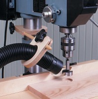
Drill Press Sawdust Collection
This is such a big enough issue that the United States Department of Labor's Occupational Safety and Health Administration (OSHA) has issued guidance and standards about it. They also noted,
Additionally, ornamental turning is usually done using woods which have a high probability of causing allergies and may even have some toxicity. Eric Meier has done a great job outlining this issue on his web site, The Wood Database. The list he has compiled contains quite a few woods commonly used.
I strongly recommend that you use a vacuum system with the intake as close to the cutting action as possible. The picture to the right shows dust collection on a drill press, but the same approach can be done on the rose engine lathe. Mine is held in a Noga arm which I move around to where it is most effective (but not intrusive).
An overhead air filtration is also recommended; something like the PowerMatic PM1200. There are other good ones, and I recommend you get such a machine when you can.
ELFOS Controls
On the Preferences page
- Ensure Returns are set correctly. Typical setting is 15,000 for all axes.
- Ensure the axis information is correct for the X & Z axes
- Distance/360 (Calculator)
- Leadscrew Left or Right
- Ensure the configurable axes are set correctly (Motor 3 & Motor 4)
- If using a Rosette Phaser/Multiplier, then for M3
- Axial
- Gear Ratio = 9
- Set as appropriate for M3 and M4
- Axial & Gear Ratio, or
- Linear
- Distance/360 (Calculator)
- Leadscrew Left or Right
- If using a Rosette Phaser/Multiplier, then for M3
|
|
|
If using multiple axes (especially on Sync or MultiSync pages), for all axes but the Spindle:
- Set max speed set to 15,000
- Set speed slider to 100%
This allows for the spindle speed slider to set the speed for all axes.
|
|
|
For the spindle, set the Max Speed as necessary. 5,000 is a recommended starting point.
|
|
|
When using the Rose pattern, for X & Z axes, set
- Max speed to 1,000-2,000
- Acceleration to 50,000
Center the Headstock
 Headstock Rocking is Set Properly |
 Headstock Rocking is Skewed to the Near Side |
 Headstock Rocking is Skewed to the Far Side |
Note: This step is only critical if you need to ensure the uniformity in a box's inside and outside surfaces. If you are not needing to do that, you may certainly skip to the next step, but this is a good idea regardless.
The steps outlined below ensure that the headstock rocks the same distance towards the far side as the near side. The diagrams shown on the below demonstrate the idea.
If the headstock rocks equally to both sides (as shown in the green above), then the planned rosette pattern will cut as expected. Conversely, if the headstock is set to rock unequally, (as shown in the red diagrams above), the pattern may be different than expected.
|
|
|
These instructions are for the MDF Rose Engine; if you are using a different machine, the parts used will be different, but the overall concept is the same.
To center the headstock's movement (rocking) as shown in the green diagram, follow the steps below. There are other methods, but this is my favorite and the easiest.
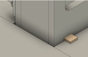 Centering Block in Use
|
 Rubber Alignment
|
Rosettes
Ensure the rosettes are
- The ones you want
- Phased correctly using a pin
- If using a rosette phaser/multiplier, held against the phaser/multiplier drive gear with a collet
Amplitude Adjuster
Ensure the amplitude adjuster
- Has the amplitude % set correctly (calculator)
- Has the arms vertically aligned
- Is using the correct shape and style of rubber to follow the rosette
- If using only one rosette, ensure the outside vertical arm is held in place, back away from the spindle.
- If using two rosettes, ensure the projection of each vertical arm rubber is correct.
Rubbers
Ensure rubbers are
- If not using an amplitude adjuster, ensure the rubber is
- The correct shape and style
- Aligned with the rosette (if not using an amplitude adjuster)
- If using two rosettes, ensure the projection of each rubber is correct.
Object
Set the object in the chuck/collet and
- Align the object in the chuck/collet
- Ensure object is being held securely (e.g., tighten the chuck/collet)
- Ensure the adapter is held securely in place with a draw bar.
- Ensure the chuck/collet is secured to the adapter.
|
|
|
Aligning the Object in the Chuck
 Object Aligned Properly 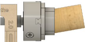 Object Misaligned |
After transferring an object from a "traditional" lathe to the rose engine lathe, there is a probability that it will not be radially or axially aligned (or both). Before making any cuts, ensure the alignment of the object whilst it turns slowly. A dial indicator is a great tool for this.
The bottom picture on the right is quite exaggerated but shows the idea of having the object misaligned.
If the rose engine's spindle has a Morse taper, and the chuck is held into place using a Morse taper adapter, then the object can be moved from one lathe to another and typically have very little misalignment. (This does assume you are not moving the object to a new chuck.) Another alternative is to use collet chucks.
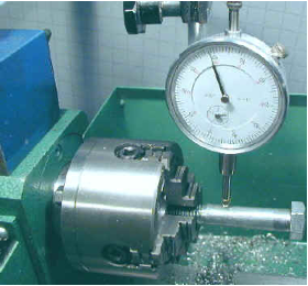
Dial Indicator in Use
Frankly, I find this the most tedious task and when first starting I sometimes wondered about the value, but it is very important. If it is not done, then the cuts on one side of the object will be different than the other side. And it will get worse the further the cuts are made from the headstock.
When using the dial indicator (held in a Noga arm or similar device), I aim for a runout as small as possible, but oftentimes it is difficult to get under 0.010". This may seem quite big, but it is hard to achieve if you do not have a leveling chuck.
The picture to the left shows a dial indicator in use on a metal lathe. A similar approach would be used on the MDF rose engine lathe, though it is recommended that the measurements be made at the end furthest from the chuck / headstock.
Slide for Tool Holding and Positioning
Follow the guidelines below based on the approach you are using.
|
|
|
Cross Slide
- Align the cross slide to be parallel to the spindle. Usually this is parallel, but an angled cut may be desired.
- Ensure there is sufficient movement on the cross slide for the needed work
- X axis
- Z axis
- Ensure the slide is held securely to the bed (e.g., mag switches engaged)
- Ensure the cutter will not cut into the collet/chuck.
Aligning the Cross Slide to the Spindle on the MDF Rose Engine
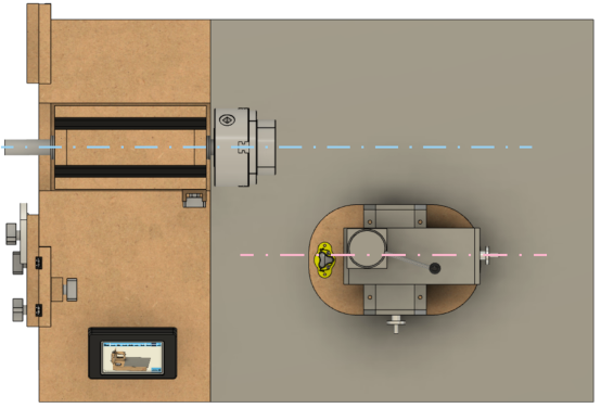
For most operations in ornamental turning, the path followed by the cross slide (the pink line) needs to be aligned on the centerline of the spindle (the red line) as shown in the picture to the right.
This allows it to work the same as the cross slide on a metal lathe (though on a metal lathe, the cross slide is attached to the lathe's bed ways).
The most accurate way to do this is with a dial indicator measuring against a straight rod affixed to the spindle (e.g., in the chuck).
Note Regarding the Lindow-White Rose Engine
The directions for doing this on a Lindow-White rose engine are in the Lindow Rose Engine Alignment Procedures, Section 4, pg. 1.
|
|
|
Curvilinear Slide
- Align the curvilinear slide to be parallel to the spindle. Usually this is parallel, but an angled cut may be desired.
- Ensure there is sufficient movement on the cross slide for the needed work
- X axis
- Z axis
- Ensure the slide is held securely to the bed (e.g., mag switches engaged)
- Template: Ensure
- The correct template is used
- The template is securely held in place
- Template Follower: Ensure
- The template follower is correct (i.e., the correct size and shape)
- The template follower is securely held in place
- The template follower is secure engaged with the template using either the weights or a spring.
|
|
|
Spherical Slide
- Set the spherical slide so that the swing achieves the desired profile
- Ensuring that the swing path is not encumbered by other objects.
- Ensure the spherical slide is held securely to the bed (e.g., mag switches engaged)
- Set the spherical slide’s puller/pusher base (the part where the motor is mounted) at the correct position
- Ensure the spherical slide’s puller/pusher base will move the cutter through the complete path needed.
- Ensure the spherical slide’s puller/pusher base is held securely to the bed (e.g., mag switches engaged)
- Ensure the slide is held securely to the bed (e.g., mag switches engaged)
|
|
|
Artistic Note
If the desire is to cut along an angle, set the alignment thusly.
Cutter of Choice
Based on the cutter you are using, the guidelines are below.
|
|
|
Cutting Frame
- For cutting frames not using the triangular, carbide cutters, ensure the cutter:
- Is the one desired
- Is at the desired projection for the needed diameter of swing
- Is held in the correct rotational position
- Is held securely
- Set the universal cutting frame’s rotation.
- Usually, this is 0° from horizontal, but it could be different if desired
- If not horizontal, ensure the rotation is the correct direction (calculator for dynamic rosette phasing)
- Align the cutter vertically (unless desired to be otherwise)
- Ensure the cutting frame is held securely in the QCTP
Choosing the Cutter to Use

Traditional Fly Cutters
The cutter you use in a cutting frame drives what is achieved from the process.
The typical cutter is either a fly cutter cut to 60° or uses a carbide insert (also at 60°).
Other angles or shapes can be used, and the ones used for fly cutting are well documented in Holtzapffel's Turning and Mechanical Manipulation, vol. 5. Some examples of these are shown to the right.
If you have multiple cutting frames, chose the one with the shortest reach which will do the job. There is no need to use one with 6" of reach when much less will get the job done. The shorter one has fewer opportunities for introducing vibrational errors.
|
|
|
Drilling Spindle
- Ensure the cutter is held securely in the collet
- Align the cutter vertically (unless desired to be otherwise)
- Ensure the drilling spindle is held securely in the QCTP
Additional Notes on the Drill Spindle

Cutter Edge Angle
Drill spindles offer a different set of options, and the shape of the drilling bit matters quite a bit. Shapes used typically follow the conventions established for milling bits.
The shape of the cutting edge is especially important when using an eccentric cutting frame. The typical fly cutter is ground with a 60° angle; however, jewelers have shown that the angle needs to be >90° for the cut so that the light is reflected back to the viewer. Otherwise, it simply looks like a set of thick dark lines. 120° is fairly common.
If your intent is to cut graining lines, then <90° may be desired.
|
|
|
Eccentric Cutting Frame
- Ensure the cutter has the correct cutting angle (e.g., 60°, 90°, 120°, etc.)
- Ensure the ECF radius is correct (calculator for pearling)
- Ensure the ECF is balanced
- If holding the ECF in a drilling spindle, see also notes above
|
|
|
Aligning the Cutter
 |
 |
|
Cutter Aligned too High | |
 |
 |
|
Cutter Aligned too Low | |
 | |
|
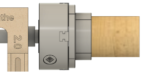
Cutter Aligned Properly | |
The cutter needs to be aligned on the centerline of the spindle as shown in the picture to the right. This can be achieved by moving the cutting frame (or drill spindle) up or down in the quick-change tool post.
You can test the cutter's alignment on the end of a piece and see how it matches up with the images of cuts to the left.
- When the cutter is aligned too high in the quick-change tool post, it will create a pattern as shown in the first row of pictures to the left.
- When the cutter is aligned too low in the quick-change tool post, it will create a pattern as shown in the second row of pictures.
- When the cutter is aligned properly, it will create a pattern as shown in the third row.
This is where the indexing function in the Control System for Multiple Stepper Motors comes in quite handy. Indexing the cuts 90° after each cut makes the alignment verification easy.
One recommendation is to affix a scrap of wood to the end of the object and make cuts into that. (It can be held there using double-sided tape.)
|
|
|
Additional Notes
The directions for aligning the cutting frame and eccentric cutting frame are in the Lindow Rose Engine Alignment Procedures. There are a number of references, so be sure to read the complete document.
|
|
|
Artistic Note
Sometimes you may want the cutter to be below or above the axis of the spindle to achieve your desired artistic effect. In that case, this step is even more important, though your target position for the cutter will be different.
Overhead Drive
- Adjust the cables to be vertical for both X and Y axes
- Ensure the cables are not too slack, nor too taut
|
|
|
Adjusting the Overhead to be Vertical

Overhead Drive Alignment on
an MDF Rose Engine
The overhead drive should be adjusted so that the drive cable has as vertical alignment as possible. The overhead drive cable is shown in the picture to the right in pink.
This only shows the view from the inboard side, but the alignment when viewed from the near side should be similarly aligned. In that case, the cable should be vertical when halfway thru the movement along the Z axis. So, it you are planning to move the cutting frame 2", then at 1", it should be vertical.
The last thing to check is that the tension on the overhead cable is right.
- Too much is not good, especially if you use the piston-style quick-change tool post as it can pull the cutting frame or drilling spindle up. (And, this will always happen at the worst possible time, destroying many hours of work.)
- Too little is also not good as it can allow the drive cable to "flop around" creating too much vibration in the cutting.
- This is also the reason you should keep the vertical distance short. Reduce the length of the cable if needed.
Cutter
 Cutting to the Left |
 Cutting to the Right |
- Ensure the cutter is being turned in the correct direction. If not, reverse the overhead drive.
|
|
|
- Set the speed for the cutter (too fast will burn certain woods, especially on the end grain)
Vacuum
Set the vacuum inlet so that
- It does not interfere with movement of the slide
- Is best able to collect most of the dust coming off the cutter
Lighting
Set the lights so that
- They do not interfere with movement of the slide
- They provide for maximum visibility of the cutting activity
- They do not shine up into the operator’s eyes
Re-check that everything is locked down
- Draw bar for work holding
- Chuck/collet to the adapter
- Object in the chuck/collet
- Slide (i.e., mag switches)
- Tool holder in QCTP
|
|
|
OK, this may seem unnecessary to state, but we speak from experience. We've all had a time when we thought we were ready to go, only to find out something wasn't right somewhere down the line.
The most common problem I've encountered is to not have the cutting frame well secured in the quick-change tool post, and the cutting frame inched its way up as the cutting goes along. But I've also had the problem where the MagSwitches were not engaged. This too became problematic at some point.
So, take the time to check to be sure everything is secured well before kicking off the cutting.
Make a Test Cut
Even when you think everything is perfect and ready to go, doing a test cut is something I like to do. This comes in one of these forms:
- When cutting down to the final form, check the pattern as you go to ensure it looks the way you envisioned. This is especially useful to ensure
- You are using the right shape for your cutter's cutting edge, and
- The radius of the cutting tool is right.
- If this is the first time you are making the object, make one out of a different (much less expensive) wood. This prototype will let you
- ensure the final form is what you want,
- ensure the sequence of cuts is the right way to approach the final form (at times I have reversed the sequence of cutting),
- ensure the approaches to the cuts is best (i.e., that the way you are holding the cutting frame relative to the object is best), and
- document the work holding.
More Information
Books and Papers
- Printable Copy of this
- The Lindow Rose Engine Alignment Procedures document is also quite useful.
|
Disclaimer: eMail comments to me at OTBookOfKnowledge @ Gmail.com. The process of woodturning involves the use of tools, machinery and materials which could cause injury or be a health hazard unless proper precautions are taken, including the wearing of appropriate protective equipment. |