Cutting Frame
Overview
 Small Universal Cutting Frame Image courtesy Fred Armbruster |

The cutting frame is similar to a circular saw or a router in the way it works: It has a spinning cutter which is engaged with the wood to cut into it.
For use, it is usually held in a quick change tool post (QCTP), and the QCTP bolted to an cross slide (much like a metal lathe's tooling is held in the compound rest).
There are many varieties of cutting frames, but the first 4 listed below are the most used today:
- horizontal cutting frame (HCF) - where the cutting head spins horizontally along a vertical axis. This is the one which is shown in the upper picture on the right.
- vertical cutting frame (VCF) - where the cutting head spins vertically along a horizontal axis.
- universal cutting frame (UCF) - where the cutting head can be rotated to the left or right, making the cutting head spin along an axis determined by the ornamental turner. This is the one which is shown in the lower picture on the right.

Figures 177-184 - Turning and
Mechanical Manipulation, vol. 5
- internal cutting frame (ICF) - which are basically drill spindles that hold a cutter perpendicular to the axis of rotation. These are particularly useful for cutting the inside of cylinders and egg-shaped objects.
- eccentric cutting frame (ECF) - a variation of the fly cutter, but the cutter's body is held in a Drill Spindle.
- elliptical cutting frame - another variation of the fly cutter.
- epicycloidal cutting frame - another variation of the fly cutter that is basically the merger of a eccentric cutting frame and a geometric chuck.
- omniversal cutting frame - this is a cutting frame used to add contrast to the cut surface without increasing the cutter radius.
- rose cutting frame - really interesting fly cutter where the cutter's holder rides along a rosette for it's movement (whilst also spinning).
Cutters Used in Cutting Frames
There are two types of cutters,
- Carbide insert cutters
- Fly cutters
Carbide insert cutters
Carbide Cutter
Image courtesy
Bill Ooms
These are triangular pieces of carbide held by a screw in the brass cutter head. They are similiar to ones used on a metal lathe. An example is shown in the picture to the right.
Advantages of using carbide cutters are:
- There are two on the wheel, making the cutting action happen twice as fast. (Brad Davis made one with three cutters.) This is far more noticeable than it would appear at first thought. It was about 6 years before I purchased one of these, and when I did I was only upset with myself for not having gotten one sooner. But is is more expensive than one with a fly cutter.
- The carbide cutters stay sharper longer.
- The carbide cutters can be easily replaced when they become dull.
The insert recommended is from Circle Machine Co., part number is 2828732 (the industry number for them is TDAB-505-C25). It is grade C25 carbide, and has a 0.007" corner radius. This radius is recommended over those cutters with 0.002" radii (or smaller).
A larger corner radius "blurs" the definition, and that may be what you want as an artist. However, a corner radius smaller than 0.007" will not necessarily give better definition. Those will amplify each and every striation in your cuts, making them look like someone dragged a rake over your workpiece.
Fly cutters

Fly Cutter
Image courtesy
Bill Ooms
Advantages of using fly cutters include:
- The fly cutters can be ground to different shapes than simply a triangular bit. This is of particular note as I have found that rounding over the end (vs. taking it to a point) makes the results better for softer woods (e.g., cherry) and woods with wider grain patters (e.g., ash).
- The fly cutters can be resharpened by the home ornamental turner. Sharpening instructions are on the are on the Sharpening Handbook web site:
- round rod fly cutters.
- traditional fly cutters
The two shapes of these are:

Traditional Fly Cutters
- Sharpened / Shaped Rods - The primary advantage of using this type of fly cutters is that the holder of the cutter can be easily made on a bench top metal lathe; no milling machine is needed.
- Shaped Flat Cutters - Traditionally, fly cutters were flat pieces of metal with various shapes, and there are some ornamental turners who use these still today. Many of these are used with vertical cutting frames, but they work on other cutting frames : It just really mattes what the turner is trying to achieve.
Some examples are shown to the right.
The smaller cutters shown in that picture would be used in internal, eccentric, elliptical, and epicycloidal cutting frames, whilst the larger would be used in vertical, horizontal, and universal cutting frames.

Slitting Saw
At the 2018 Ornamental Turners International Symposium, Steve White introduced the idea of using slitting saws in a cutting frame. These are the same saws that get used in milling machines for cutting slits in an object.
Steve's use of this was to cut a slit of a certain size (say, 1/16") along the Z axis in an object at various locations (e.g., every 90° around the circumference), and then insert a piece of contrasting wood into the slit. This is different from segments glued together with thin contrasting woods. In this case, the slits did not traverse the entire length of the piece, only a part of it. (I realize a picture would be great, and I'm working on getting one.) It is a great way to produce a uniformity and beauty that couldn't be easily done via other methods.
The cutting head is traditionally rotated using an overhead drive, but direct drive approaches are also used.
Cutting frames can be purchased from a number of vendors, or you can make your own. Directions for making a cutting frame are nicely described by Bill Ooms. There are additional notes about this at making a cutting frame.
If you make your own, you will need belting for it (that is the orange stuff in the universal cutting frame picture, above). I used the same cable belting for this as I used on my overhead drive.
Examples of this device in use
- This YouTube video, MDF Rose Engine Lathe : #5 - Horizontal Cutting Frame, shows a horizontal cutting frame in use.
- This YouTube video, Fly Cutter for a Rose Engine Ornamental Lathe, shows a fly cutter in use.
- This YouTube video, MDF Rose Engine Lathe : #8 - Making & Sharpening Fly Cutters, shows how I make and sharpen a rod-based fly cutter.
Usage Notes
 |
 |
|
Cutter Aligned too High | |
 |
 |
|
Cutter Aligned too Low | |
 | |
|
Cutter Aligned Properly | |
The cutter needs to be aligned on the centerline of the spindle as shown in the picture to the right. This can be achieved by moving the cutting frame (or drill spindle) up or down in the quick-change tool post.
You can test the cutter's alignment on the end of a piece and see how it matches up with the images of cuts to the left.
- When the cutter is aligned too high in the quick-change tool post, it will create a pattern as shown in the first row of pictures to the left.
- When the cutter is aligned too low in the quick-change tool post, it will create a pattern as shown in the second row of pictures.
- When the cutter is aligned properly, it will create a pattern as shown in the third row.
This is where the indexing function in the Control System for Multiple Stepper Motors comes in quite handy. Indexing the cuts 90° after each cut makes the alignment verification easy.
One recommendation is to affix a scrap of wood to the end of the object and make cuts into that. (It can be held there using double-sided tape.)
Additional Notes
The directions for aligning the cutting frame and eccentric cutting frame are in the Lindow Rose Engine Alignment Procedures. There are a number of references, so be sure to read the complete document.
Artistic Note
Sometimes you may want the cutter to be below or above the axis of the spindle to achieve your desired artistic effect. In that case, this step is even more important, though your target position for the cutter will be different.
Rotating the Cutter

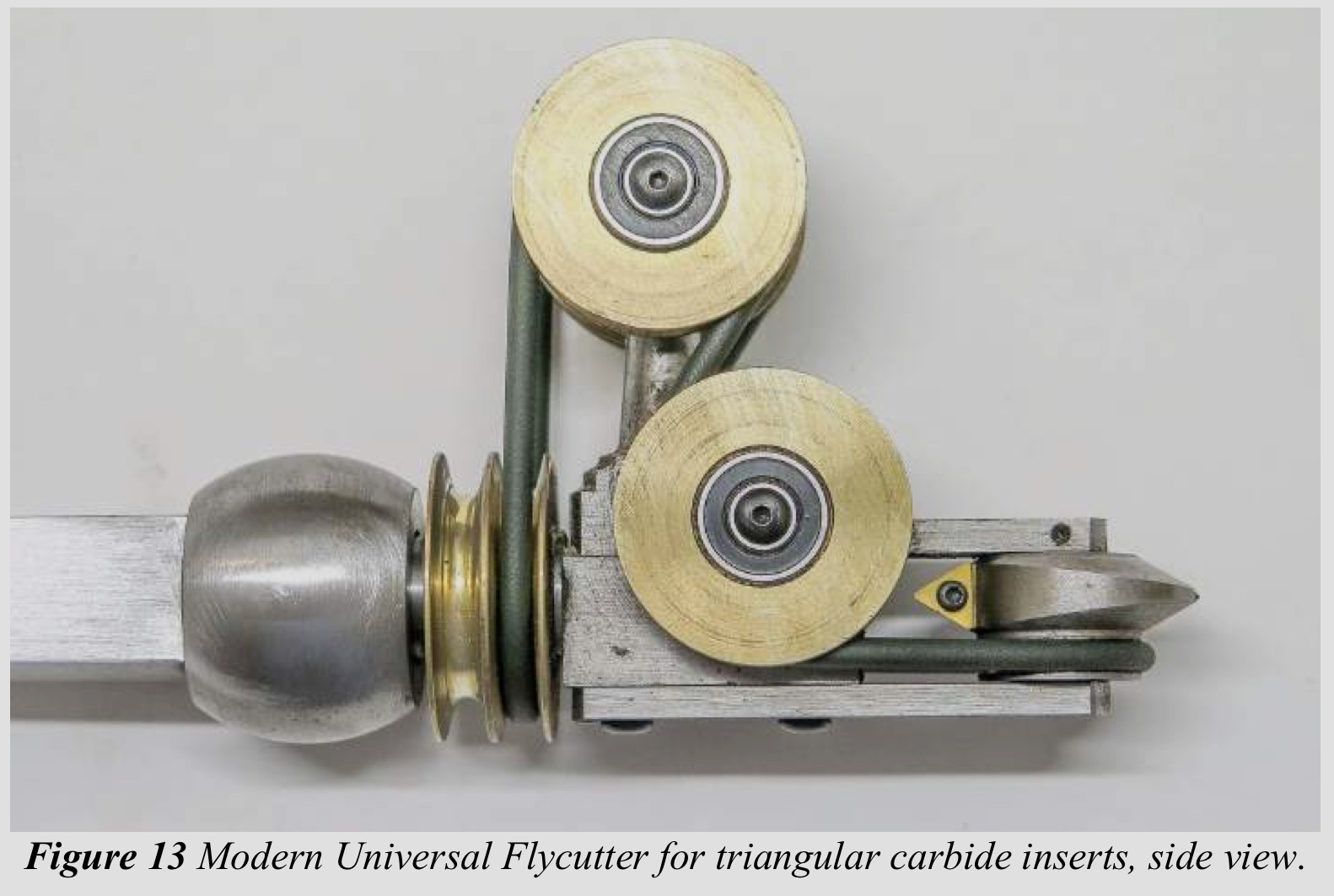
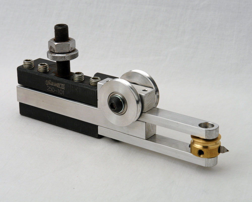
Universal Cutting Frame
The picture to the right shows a typical, home-made universal cutting frame from the side and the end. This UCF has a fly cutter, and the axis of rotation of the fly cutter is not aligned with the axis of rotation of the cutting frame. Other cutting frames are not made with such a difference, but many home-made cutting frames have this.
The dashed lines show the two centers of rotation.
- The blue line represents the rotation axis for the universal cutting frame.
- The red line represents the rotation axis for the cutter in the universal cutting frame.

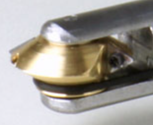
Rotating the Universal Cutting Frame
When we say that the cutter is aligned with the object, the cutter's axis of rotation (the red line) is aligned with the spindle's axis of rotation (the green line). This UCF's manufacture does not have the axis for the cutter and the axis for the UCF aligned, so when the UCF is rotated, there will be a change in where the cutter cuts the object.
The picture to the left bottom shows the cutter rotated 45°. As shown, the horizontal centerline for the cutter is now closer to the centerline for the UCF. If the cutter is not raised in the tool holder, then the cutter will be cutting below the axis of rotation on the piece being cut. In this example, rotating the cutter 45° moves red line to be closer to the blue line, and the distance between the lines has been reduced by ~29%. For example:
|
NewGap = OriginalGap x (1-sin(Rotation)) NewGap = 0.125” x (1 - sin(45°)) NewGap = 0.088” |
The cutter's center for rotation is aligned 0.037” lower than before, and that difference will be quite noticeable.
 Cutter Aligned above spindle's axis of rotation |
 Cutter Aligned on spindle's axis of rotation |
This means there is some distance between the axis of rotation for the cutter vs. the axis of rotation for the UCF. This distance is indicated by the two arrows in the picture to the left. The screw on the tool holder in the quick change tool post is used to adjust this vertical alignment. A machinist height gauge can assist with the adjustment.
If the cutter's vertical alignment is not adjusted, the resulting cuts will be different than possibly expected. The picture to the right shows the effect of having the cutter aligned above and on the spindle's axis of rotation.
Cutter Rotational Speed
When I was getting started with ornamental turning, I asked how fast the cutter should be spun. The gentleman responded, "I run it as fast as I can without burning the wood."
It is common to use a variable speed motor like the midi lathe conversion kit from Penn State Industries for the overhead drive. To drive the belt, it is also common to use a multi-step pulley, with the pulley sizes at 4", 3", and 2" diameter. Based on that, the 4" pulley is used most often, and the 2" one almost never.
General ideas are:
- low density woods (like walnut) - run the cutter at maximum speed
- high density woods like ironwood - run the cutter at medium speed
- end grain on woods prone to burning (like maple) - run the cutter at slower speed
Additional notes regarding materials used in ornamental turning are captured in the materials section of this site.
Maintenance & Preventative Maintenance Notes

Field-expedient dust cover
It is a good practice on the Lindow universal cutting frame to add a drop of thin oil (e.g., sewing machine oil) to the cutter head bearing, and then cover the opening. The picture to the right shows how tape is used to cover the bearing opening (only the top side is shown; the bottom side is the same - you can click on the picture to see a larger version).
This preventative measure will help significantly reduce the dust which gets into the bearing when being used.
(Thank you to Roy Lindley for noting this. He noted that he saw this on Scott Barrett's UCF.)
Notes on making one
Key Note: Cutting Frames are where the quality of ornamental cutting comes to life. If there is vibration in the cutting frame it will be transmitted to the cuts, and the quality of the work will be poor.
When you are using the rose engine lathe, listen for noise in the cutting frame. The cutting frame should have a whir like a finely tuned machine, and the noise level should be low. If there is vibration, the noise level will be higher; sometimes much higher and the tone of the noise will be higher. It won't sound or run like a finely tuned machine.
Cutting Frames are not hard to make if you have a metal lathe (or access to one). A milling machine is also useful, but not required.
- Bill Ooms provided great directions on making cutting frames, especially the UCF. I have used these plans, and additional notes from my own experiences making an HCF are on this web page.
 Horizontal Cutting |
 Vertical Cutting |
 Right Angle Cutting |
- Ed French published directions for making a number of cutting frame designs on his GitHub page (pictures of one design are below to the right). The advantages to what Ed has published is that his designs are published as both PDF images and Fusion 360 models.
- Fred Connell & Roland Hege have also outlined directions for making one at www.OrnamentalRoseEngine.com.
Some Things to Consider
- The cutting head should probably be made from steel. It needs to hold the cutter very firmly.
- The cutting head needs to be held firmly in the bearings; it can't be flopping around or your cuts will be sloppy
- The cutting head needs to spin freely in the bearings. It will be turning at a high rate for quite a while and can heat up. It is easy for some to seem like they have seized up when the bearings are just too tight when everything is hot.
- Set the bearing sizes to match the size of the cutter.
- For smaller rods like 1/8", the bearings can be smaller.
- For larger rods like 6mm, the bearings need to be substantial.
- If you are making a universal cutting frame, aim for the plane of the cutter's rotation to be on the axis of the cutting head's rotation. (There are more details about this above.)
3D-Printable Cutting Frames
Ed French developed a UCF which can be 3D-printed. The files needed are on his GitHub page.
Sources for buying one
- Dr. Fred Armbruster - Instagram - otbirch, or eMail otdeity@gmail.com
- Lindow Rose Engine, LLC
Sources for buying cutters for one
- For the fly cutters:
- Ornamental Tools from Chris Ploof Designs makes some really neat designs.
- Jon Spencer also makes some nice designs. You can contact him at jspencer.co@gmail.com.
- For the carbide inserts, consider Circle Machine Company's part number is 2828732 (the industry number for them is TDAB-505-C25). It is grade C25 carbide, and has a 0.007" corner radius. You will need to search for a source for this on the Internet: Circle Machine Company does not seem to sell directly to the public.
Specifications and Replacement Parts for Commonly Available Cutting Frames
Brad Davis’ UCF | ||||||||||||||||||||||||||||||||||||||||||||||||||||||||||||||||||||||||||||||||||||||||||||||||||||||||||||||||||||||||||||||||||||||||||||||||||||||||||||||||||||||||||||||||||||||||||||||||||||||||||||||||||||||||||||||||||||||||||||||||||||||||||||||||||||||||||||||||||||||||||||||||||||||||||||||||||||||||||||||||||||||||||||||||||||||||||||||||||||||||||||||||||||||||||||||||||||||||||||||||||||||||||||||||||||||||||||||||||||||||||||||||||||||||||||||||||||||||||||||||||||||||||||||||||||||||||||||||||||||||||||||||||||||||||||||||||||||||||||||||||||||||||||||||||||||||||||||||||||||||||||||||||||||||||||||||||||||||||||||||||||||||||||||||||||||||||||||||||||||||||||||||||||||||||||||||||||||||||||||||||||||||||||||||||||||||||||||||||||||||||||||||||||||||||||||||||||||||||||||||||||||||||||||||||||||||||||||||||||||||||||||||||||||||||||||||||||||||||||||||||||||||||||||||||||||||||||||||||||||||||||||||||||||||||||||||||||||||||||||||||||||||||||||||||||||||||||||||||||||
|
|
Overhead Drive Cable |
4mm (~⅛”) round belting. Habasit textured belting recommended. | ||||||||||||||||||||||||||||||||||||||||||||||||||||||||||||||||||||||||||||||||||||||||||||||||||||||||||||||||||||||||||||||||||||||||||||||||||||||||||||||||||||||||||||||||||||||||||||||||||||||||||||||||||||||||||||||||||||||||||||||||||||||||||||||||||||||||||||||||||||||||||||||||||||||||||||||||||||||||||||||||||||||||||||||||||||||||||||||||||||||||||||||||||||||||||||||||||||||||||||||||||||||||||||||||||||||||||||||||||||||||||||||||||||||||||||||||||||||||||||||||||||||||||||||||||||||||||||||||||||||||||||||||||||||||||||||||||||||||||||||||||||||||||||||||||||||||||||||||||||||||||||||||||||||||||||||||||||||||||||||||||||||||||||||||||||||||||||||||||||||||||||||||||||||||||||||||||||||||||||||||||||||||||||||||||||||||||||||||||||||||||||||||||||||||||||||||||||||||||||||||||||||||||||||||||||||||||||||||||||||||||||||||||||||||||||||||||||||||||||||||||||||||||||||||||||||||||||||||||||||||||||||||||||||||||||||||||||||||||||||||||||||||||||||||||||||||||||||||||||
|
|
Secondary Cable |
2mm round belting. Habasit textured belting recommended. | ||||||||||||||||||||||||||||||||||||||||||||||||||||||||||||||||||||||||||||||||||||||||||||||||||||||||||||||||||||||||||||||||||||||||||||||||||||||||||||||||||||||||||||||||||||||||||||||||||||||||||||||||||||||||||||||||||||||||||||||||||||||||||||||||||||||||||||||||||||||||||||||||||||||||||||||||||||||||||||||||||||||||||||||||||||||||||||||||||||||||||||||||||||||||||||||||||||||||||||||||||||||||||||||||||||||||||||||||||||||||||||||||||||||||||||||||||||||||||||||||||||||||||||||||||||||||||||||||||||||||||||||||||||||||||||||||||||||||||||||||||||||||||||||||||||||||||||||||||||||||||||||||||||||||||||||||||||||||||||||||||||||||||||||||||||||||||||||||||||||||||||||||||||||||||||||||||||||||||||||||||||||||||||||||||||||||||||||||||||||||||||||||||||||||||||||||||||||||||||||||||||||||||||||||||||||||||||||||||||||||||||||||||||||||||||||||||||||||||||||||||||||||||||||||||||||||||||||||||||||||||||||||||||||||||||||||||||||||||||||||||||||||||||||||||||||||||||||||||||
|
|
Cutter Head Bearings |
Dynaroll High Precision Ball Bearing, R2-2Z, Stainless Steel, ABEC 5 | ||||||||||||||||||||||||||||||||||||||||||||||||||||||||||||||||||||||||||||||||||||||||||||||||||||||||||||||||||||||||||||||||||||||||||||||||||||||||||||||||||||||||||||||||||||||||||||||||||||||||||||||||||||||||||||||||||||||||||||||||||||||||||||||||||||||||||||||||||||||||||||||||||||||||||||||||||||||||||||||||||||||||||||||||||||||||||||||||||||||||||||||||||||||||||||||||||||||||||||||||||||||||||||||||||||||||||||||||||||||||||||||||||||||||||||||||||||||||||||||||||||||||||||||||||||||||||||||||||||||||||||||||||||||||||||||||||||||||||||||||||||||||||||||||||||||||||||||||||||||||||||||||||||||||||||||||||||||||||||||||||||||||||||||||||||||||||||||||||||||||||||||||||||||||||||||||||||||||||||||||||||||||||||||||||||||||||||||||||||||||||||||||||||||||||||||||||||||||||||||||||||||||||||||||||||||||||||||||||||||||||||||||||||||||||||||||||||||||||||||||||||||||||||||||||||||||||||||||||||||||||||||||||||||||||||||||||||||||||||||||||||||||||||||||||||||||||||||||||||
|
|
UCF Pulley Bearings |
R-188-2Z Flange Bearing, Stainless Steel, ABEC 5 | ||||||||||||||||||||||||||||||||||||||||||||||||||||||||||||||||||||||||||||||||||||||||||||||||||||||||||||||||||||||||||||||||||||||||||||||||||||||||||||||||||||||||||||||||||||||||||||||||||||||||||||||||||||||||||||||||||||||||||||||||||||||||||||||||||||||||||||||||||||||||||||||||||||||||||||||||||||||||||||||||||||||||||||||||||||||||||||||||||||||||||||||||||||||||||||||||||||||||||||||||||||||||||||||||||||||||||||||||||||||||||||||||||||||||||||||||||||||||||||||||||||||||||||||||||||||||||||||||||||||||||||||||||||||||||||||||||||||||||||||||||||||||||||||||||||||||||||||||||||||||||||||||||||||||||||||||||||||||||||||||||||||||||||||||||||||||||||||||||||||||||||||||||||||||||||||||||||||||||||||||||||||||||||||||||||||||||||||||||||||||||||||||||||||||||||||||||||||||||||||||||||||||||||||||||||||||||||||||||||||||||||||||||||||||||||||||||||||||||||||||||||||||||||||||||||||||||||||||||||||||||||||||||||||||||||||||||||||||||||||||||||||||||||||||||||||||||||||||||||
|
|
Cutters |
Widia C25 Insert | ||||||||||||||||||||||||||||||||||||||||||||||||||||||||||||||||||||||||||||||||||||||||||||||||||||||||||||||||||||||||||||||||||||||||||||||||||||||||||||||||||||||||||||||||||||||||||||||||||||||||||||||||||||||||||||||||||||||||||||||||||||||||||||||||||||||||||||||||||||||||||||||||||||||||||||||||||||||||||||||||||||||||||||||||||||||||||||||||||||||||||||||||||||||||||||||||||||||||||||||||||||||||||||||||||||||||||||||||||||||||||||||||||||||||||||||||||||||||||||||||||||||||||||||||||||||||||||||||||||||||||||||||||||||||||||||||||||||||||||||||||||||||||||||||||||||||||||||||||||||||||||||||||||||||||||||||||||||||||||||||||||||||||||||||||||||||||||||||||||||||||||||||||||||||||||||||||||||||||||||||||||||||||||||||||||||||||||||||||||||||||||||||||||||||||||||||||||||||||||||||||||||||||||||||||||||||||||||||||||||||||||||||||||||||||||||||||||||||||||||||||||||||||||||||||||||||||||||||||||||||||||||||||||||||||||||||||||||||||||||||||||||||||||||||||||||||||||||||||||
|
|
Cutter Screw |
Widia Insert Screw for Indexables: T7 Torx, #2-56 Thread p/n 2830477 | ||||||||||||||||||||||||||||||||||||||||||||||||||||||||||||||||||||||||||||||||||||||||||||||||||||||||||||||||||||||||||||||||||||||||||||||||||||||||||||||||||||||||||||||||||||||||||||||||||||||||||||||||||||||||||||||||||||||||||||||||||||||||||||||||||||||||||||||||||||||||||||||||||||||||||||||||||||||||||||||||||||||||||||||||||||||||||||||||||||||||||||||||||||||||||||||||||||||||||||||||||||||||||||||||||||||||||||||||||||||||||||||||||||||||||||||||||||||||||||||||||||||||||||||||||||||||||||||||||||||||||||||||||||||||||||||||||||||||||||||||||||||||||||||||||||||||||||||||||||||||||||||||||||||||||||||||||||||||||||||||||||||||||||||||||||||||||||||||||||||||||||||||||||||||||||||||||||||||||||||||||||||||||||||||||||||||||||||||||||||||||||||||||||||||||||||||||||||||||||||||||||||||||||||||||||||||||||||||||||||||||||||||||||||||||||||||||||||||||||||||||||||||||||||||||||||||||||||||||||||||||||||||||||||||||||||||||||||||||||||||||||||||||||||||||||||||||||||||||||
|
|
Spacer Shims |
0.014” thick x 0.125” ID x 0.187” OD 0.005” thick x 0.125” ID x 0.187” OD (additional, and as needed for the top) | ||||||||||||||||||||||||||||||||||||||||||||||||||||||||||||||||||||||||||||||||||||||||||||||||||||||||||||||||||||||||||||||||||||||||||||||||||||||||||||||||||||||||||||||||||||||||||||||||||||||||||||||||||||||||||||||||||||||||||||||||||||||||||||||||||||||||||||||||||||||||||||||||||||||||||||||||||||||||||||||||||||||||||||||||||||||||||||||||||||||||||||||||||||||||||||||||||||||||||||||||||||||||||||||||||||||||||||||||||||||||||||||||||||||||||||||||||||||||||||||||||||||||||||||||||||||||||||||||||||||||||||||||||||||||||||||||||||||||||||||||||||||||||||||||||||||||||||||||||||||||||||||||||||||||||||||||||||||||||||||||||||||||||||||||||||||||||||||||||||||||||||||||||||||||||||||||||||||||||||||||||||||||||||||||||||||||||||||||||||||||||||||||||||||||||||||||||||||||||||||||||||||||||||||||||||||||||||||||||||||||||||||||||||||||||||||||||||||||||||||||||||||||||||||||||||||||||||||||||||||||||||||||||||||||||||||||||||||||||||||||||||||||||||||||||||||||||||||||||||
|
|
Comments
| |||||||||||||||||||||||||||||||||||||||||||||||||||||||||||||||||||||||||||||||||||||||||||||||||||||||||||||||||||||||||||||||||||||||||||||||||||||||||||||||||||||||||||||||||||||||||||||||||||||||||||||||||||||||||||||||||||||||||||||||||||||||||||||||||||||||||||||||||||||||||||||||||||||||||||||||||||||||||||||||||||||||||||||||||||||||||||||||||||||||||||||||||||||||||||||||||||||||||||||||||||||||||||||||||||||||||||||||||||||||||||||||||||||||||||||||||||||||||||||||||||||||||||||||||||||||||||||||||||||||||||||||||||||||||||||||||||||||||||||||||||||||||||||||||||||||||||||||||||||||||||||||||||||||||||||||||||||||||||||||||||||||||||||||||||||||||||||||||||||||||||||||||||||||||||||||||||||||||||||||||||||||||||||||||||||||||||||||||||||||||||||||||||||||||||||||||||||||||||||||||||||||||||||||||||||||||||||||||||||||||||||||||||||||||||||||||||||||||||||||||||||||||||||||||||||||||||||||||||||||||||||||||||||||||||||||||||||||||||||||||||||||||||||||||||||||||||||||||||||
Fred Armbuster’s ‘Jack of All Trades’ UCF | ||||||||||||||||||||||||||||||||||||||||||||||||||||||||||||||||||||||||||||||||||||||||||||||||||||||||||||||||||||||||||||||||||||||||||||||||||||||||||||||||||||||||||||||||||||||||||||||||||||||||||||||||||||||||||||||||||||||||||||||||||||||||||||||||||||||||||||||||||||||||||||||||||||||||||||||||||||||||||||||||||||||||||||||||||||||||||||||||||||||||||||||||||||||||||||||||||||||||||||||||||||||||||||||||||||||||||||||||||||||||||||||||||||||||||||||||||||||||||||||||||||||||||||||||||||||||||||||||||||||||||||||||||||||||||||||||||||||||||||||||||||||||||||||||||||||||||||||||||||||||||||||||||||||||||||||||||||||||||||||||||||||||||||||||||||||||||||||||||||||||||||||||||||||||||||||||||||||||||||||||||||||||||||||||||||||||||||||||||||||||||||||||||||||||||||||||||||||||||||||||||||||||||||||||||||||||||||||||||||||||||||||||||||||||||||||||||||||||||||||||||||||||||||||||||||||||||||||||||||||||||||||||||||||||||||||||||||||||||||||||||||||||||||||||||||||||||||||||||||||
|
|
Overhead Drive Cable |
4mm (~⅛”) round belting. Habasit textured belting recommended. | ||||||||||||||||||||||||||||||||||||||||||||||||||||||||||||||||||||||||||||||||||||||||||||||||||||||||||||||||||||||||||||||||||||||||||||||||||||||||||||||||||||||||||||||||||||||||||||||||||||||||||||||||||||||||||||||||||||||||||||||||||||||||||||||||||||||||||||||||||||||||||||||||||||||||||||||||||||||||||||||||||||||||||||||||||||||||||||||||||||||||||||||||||||||||||||||||||||||||||||||||||||||||||||||||||||||||||||||||||||||||||||||||||||||||||||||||||||||||||||||||||||||||||||||||||||||||||||||||||||||||||||||||||||||||||||||||||||||||||||||||||||||||||||||||||||||||||||||||||||||||||||||||||||||||||||||||||||||||||||||||||||||||||||||||||||||||||||||||||||||||||||||||||||||||||||||||||||||||||||||||||||||||||||||||||||||||||||||||||||||||||||||||||||||||||||||||||||||||||||||||||||||||||||||||||||||||||||||||||||||||||||||||||||||||||||||||||||||||||||||||||||||||||||||||||||||||||||||||||||||||||||||||||||||||||||||||||||||||||||||||||||||||||||||||||||||||||||||||||||
|
|
Secondary Cable |
2mm round belting. Habasit textured belting recommended. | ||||||||||||||||||||||||||||||||||||||||||||||||||||||||||||||||||||||||||||||||||||||||||||||||||||||||||||||||||||||||||||||||||||||||||||||||||||||||||||||||||||||||||||||||||||||||||||||||||||||||||||||||||||||||||||||||||||||||||||||||||||||||||||||||||||||||||||||||||||||||||||||||||||||||||||||||||||||||||||||||||||||||||||||||||||||||||||||||||||||||||||||||||||||||||||||||||||||||||||||||||||||||||||||||||||||||||||||||||||||||||||||||||||||||||||||||||||||||||||||||||||||||||||||||||||||||||||||||||||||||||||||||||||||||||||||||||||||||||||||||||||||||||||||||||||||||||||||||||||||||||||||||||||||||||||||||||||||||||||||||||||||||||||||||||||||||||||||||||||||||||||||||||||||||||||||||||||||||||||||||||||||||||||||||||||||||||||||||||||||||||||||||||||||||||||||||||||||||||||||||||||||||||||||||||||||||||||||||||||||||||||||||||||||||||||||||||||||||||||||||||||||||||||||||||||||||||||||||||||||||||||||||||||||||||||||||||||||||||||||||||||||||||||||||||||||||||||||||||||
|
|
UCF Pulley Bearings |
R-3-2Z Bearing, Stainless Steel, Shielded, ABEC 5 | ||||||||||||||||||||||||||||||||||||||||||||||||||||||||||||||||||||||||||||||||||||||||||||||||||||||||||||||||||||||||||||||||||||||||||||||||||||||||||||||||||||||||||||||||||||||||||||||||||||||||||||||||||||||||||||||||||||||||||||||||||||||||||||||||||||||||||||||||||||||||||||||||||||||||||||||||||||||||||||||||||||||||||||||||||||||||||||||||||||||||||||||||||||||||||||||||||||||||||||||||||||||||||||||||||||||||||||||||||||||||||||||||||||||||||||||||||||||||||||||||||||||||||||||||||||||||||||||||||||||||||||||||||||||||||||||||||||||||||||||||||||||||||||||||||||||||||||||||||||||||||||||||||||||||||||||||||||||||||||||||||||||||||||||||||||||||||||||||||||||||||||||||||||||||||||||||||||||||||||||||||||||||||||||||||||||||||||||||||||||||||||||||||||||||||||||||||||||||||||||||||||||||||||||||||||||||||||||||||||||||||||||||||||||||||||||||||||||||||||||||||||||||||||||||||||||||||||||||||||||||||||||||||||||||||||||||||||||||||||||||||||||||||||||||||||||||||||||||||||
Fred Armbuster’s Small Diameter HCF with 0.0625” Cutter | ||||||||||||||||||||||||||||||||||||||||||||||||||||||||||||||||||||||||||||||||||||||||||||||||||||||||||||||||||||||||||||||||||||||||||||||||||||||||||||||||||||||||||||||||||||||||||||||||||||||||||||||||||||||||||||||||||||||||||||||||||||||||||||||||||||||||||||||||||||||||||||||||||||||||||||||||||||||||||||||||||||||||||||||||||||||||||||||||||||||||||||||||||||||||||||||||||||||||||||||||||||||||||||||||||||||||||||||||||||||||||||||||||||||||||||||||||||||||||||||||||||||||||||||||||||||||||||||||||||||||||||||||||||||||||||||||||||||||||||||||||||||||||||||||||||||||||||||||||||||||||||||||||||||||||||||||||||||||||||||||||||||||||||||||||||||||||||||||||||||||||||||||||||||||||||||||||||||||||||||||||||||||||||||||||||||||||||||||||||||||||||||||||||||||||||||||||||||||||||||||||||||||||||||||||||||||||||||||||||||||||||||||||||||||||||||||||||||||||||||||||||||||||||||||||||||||||||||||||||||||||||||||||||||||||||||||||||||||||||||||||||||||||||||||||||||||||||||||||||||
|
|
Overhead Drive Cable |
2mm round belting. Habasit textured belting recommended. | ||||||||||||||||||||||||||||||||||||||||||||||||||||||||||||||||||||||||||||||||||||||||||||||||||||||||||||||||||||||||||||||||||||||||||||||||||||||||||||||||||||||||||||||||||||||||||||||||||||||||||||||||||||||||||||||||||||||||||||||||||||||||||||||||||||||||||||||||||||||||||||||||||||||||||||||||||||||||||||||||||||||||||||||||||||||||||||||||||||||||||||||||||||||||||||||||||||||||||||||||||||||||||||||||||||||||||||||||||||||||||||||||||||||||||||||||||||||||||||||||||||||||||||||||||||||||||||||||||||||||||||||||||||||||||||||||||||||||||||||||||||||||||||||||||||||||||||||||||||||||||||||||||||||||||||||||||||||||||||||||||||||||||||||||||||||||||||||||||||||||||||||||||||||||||||||||||||||||||||||||||||||||||||||||||||||||||||||||||||||||||||||||||||||||||||||||||||||||||||||||||||||||||||||||||||||||||||||||||||||||||||||||||||||||||||||||||||||||||||||||||||||||||||||||||||||||||||||||||||||||||||||||||||||||||||||||||||||||||||||||||||||||||||||||||||||||||||||||||||
|
|
Cutter Head Bearings |
0.156” diameter | ||||||||||||||||||||||||||||||||||||||||||||||||||||||||||||||||||||||||||||||||||||||||||||||||||||||||||||||||||||||||||||||||||||||||||||||||||||||||||||||||||||||||||||||||||||||||||||||||||||||||||||||||||||||||||||||||||||||||||||||||||||||||||||||||||||||||||||||||||||||||||||||||||||||||||||||||||||||||||||||||||||||||||||||||||||||||||||||||||||||||||||||||||||||||||||||||||||||||||||||||||||||||||||||||||||||||||||||||||||||||||||||||||||||||||||||||||||||||||||||||||||||||||||||||||||||||||||||||||||||||||||||||||||||||||||||||||||||||||||||||||||||||||||||||||||||||||||||||||||||||||||||||||||||||||||||||||||||||||||||||||||||||||||||||||||||||||||||||||||||||||||||||||||||||||||||||||||||||||||||||||||||||||||||||||||||||||||||||||||||||||||||||||||||||||||||||||||||||||||||||||||||||||||||||||||||||||||||||||||||||||||||||||||||||||||||||||||||||||||||||||||||||||||||||||||||||||||||||||||||||||||||||||||||||||||||||||||||||||||||||||||||||||||||||||||||||||||||||||||
|
|
Cutters |
Carbide rod, 0.0625” diameter, 0.375” long | ||||||||||||||||||||||||||||||||||||||||||||||||||||||||||||||||||||||||||||||||||||||||||||||||||||||||||||||||||||||||||||||||||||||||||||||||||||||||||||||||||||||||||||||||||||||||||||||||||||||||||||||||||||||||||||||||||||||||||||||||||||||||||||||||||||||||||||||||||||||||||||||||||||||||||||||||||||||||||||||||||||||||||||||||||||||||||||||||||||||||||||||||||||||||||||||||||||||||||||||||||||||||||||||||||||||||||||||||||||||||||||||||||||||||||||||||||||||||||||||||||||||||||||||||||||||||||||||||||||||||||||||||||||||||||||||||||||||||||||||||||||||||||||||||||||||||||||||||||||||||||||||||||||||||||||||||||||||||||||||||||||||||||||||||||||||||||||||||||||||||||||||||||||||||||||||||||||||||||||||||||||||||||||||||||||||||||||||||||||||||||||||||||||||||||||||||||||||||||||||||||||||||||||||||||||||||||||||||||||||||||||||||||||||||||||||||||||||||||||||||||||||||||||||||||||||||||||||||||||||||||||||||||||||||||||||||||||||||||||||||||||||||||||||||||||||||||||||||||||
|
|
Comments
| |||||||||||||||||||||||||||||||||||||||||||||||||||||||||||||||||||||||||||||||||||||||||||||||||||||||||||||||||||||||||||||||||||||||||||||||||||||||||||||||||||||||||||||||||||||||||||||||||||||||||||||||||||||||||||||||||||||||||||||||||||||||||||||||||||||||||||||||||||||||||||||||||||||||||||||||||||||||||||||||||||||||||||||||||||||||||||||||||||||||||||||||||||||||||||||||||||||||||||||||||||||||||||||||||||||||||||||||||||||||||||||||||||||||||||||||||||||||||||||||||||||||||||||||||||||||||||||||||||||||||||||||||||||||||||||||||||||||||||||||||||||||||||||||||||||||||||||||||||||||||||||||||||||||||||||||||||||||||||||||||||||||||||||||||||||||||||||||||||||||||||||||||||||||||||||||||||||||||||||||||||||||||||||||||||||||||||||||||||||||||||||||||||||||||||||||||||||||||||||||||||||||||||||||||||||||||||||||||||||||||||||||||||||||||||||||||||||||||||||||||||||||||||||||||||||||||||||||||||||||||||||||||||||||||||||||||||||||||||||||||||||||||||||||||||||||||||||||||||||
Fred Armbuster’s Small Diameter HCF with Small Carbide Insert | ||||||||||||||||||||||||||||||||||||||||||||||||||||||||||||||||||||||||||||||||||||||||||||||||||||||||||||||||||||||||||||||||||||||||||||||||||||||||||||||||||||||||||||||||||||||||||||||||||||||||||||||||||||||||||||||||||||||||||||||||||||||||||||||||||||||||||||||||||||||||||||||||||||||||||||||||||||||||||||||||||||||||||||||||||||||||||||||||||||||||||||||||||||||||||||||||||||||||||||||||||||||||||||||||||||||||||||||||||||||||||||||||||||||||||||||||||||||||||||||||||||||||||||||||||||||||||||||||||||||||||||||||||||||||||||||||||||||||||||||||||||||||||||||||||||||||||||||||||||||||||||||||||||||||||||||||||||||||||||||||||||||||||||||||||||||||||||||||||||||||||||||||||||||||||||||||||||||||||||||||||||||||||||||||||||||||||||||||||||||||||||||||||||||||||||||||||||||||||||||||||||||||||||||||||||||||||||||||||||||||||||||||||||||||||||||||||||||||||||||||||||||||||||||||||||||||||||||||||||||||||||||||||||||||||||||||||||||||||||||||||||||||||||||||||||||||||||||||||||||
|
|
Overhead Drive Cable |
2mm round belting. Habasit textured belting recommended. | ||||||||||||||||||||||||||||||||||||||||||||||||||||||||||||||||||||||||||||||||||||||||||||||||||||||||||||||||||||||||||||||||||||||||||||||||||||||||||||||||||||||||||||||||||||||||||||||||||||||||||||||||||||||||||||||||||||||||||||||||||||||||||||||||||||||||||||||||||||||||||||||||||||||||||||||||||||||||||||||||||||||||||||||||||||||||||||||||||||||||||||||||||||||||||||||||||||||||||||||||||||||||||||||||||||||||||||||||||||||||||||||||||||||||||||||||||||||||||||||||||||||||||||||||||||||||||||||||||||||||||||||||||||||||||||||||||||||||||||||||||||||||||||||||||||||||||||||||||||||||||||||||||||||||||||||||||||||||||||||||||||||||||||||||||||||||||||||||||||||||||||||||||||||||||||||||||||||||||||||||||||||||||||||||||||||||||||||||||||||||||||||||||||||||||||||||||||||||||||||||||||||||||||||||||||||||||||||||||||||||||||||||||||||||||||||||||||||||||||||||||||||||||||||||||||||||||||||||||||||||||||||||||||||||||||||||||||||||||||||||||||||||||||||||||||||||||||||||||||
|
|
Cutter Head Bearings |
0.156” diameter | ||||||||||||||||||||||||||||||||||||||||||||||||||||||||||||||||||||||||||||||||||||||||||||||||||||||||||||||||||||||||||||||||||||||||||||||||||||||||||||||||||||||||||||||||||||||||||||||||||||||||||||||||||||||||||||||||||||||||||||||||||||||||||||||||||||||||||||||||||||||||||||||||||||||||||||||||||||||||||||||||||||||||||||||||||||||||||||||||||||||||||||||||||||||||||||||||||||||||||||||||||||||||||||||||||||||||||||||||||||||||||||||||||||||||||||||||||||||||||||||||||||||||||||||||||||||||||||||||||||||||||||||||||||||||||||||||||||||||||||||||||||||||||||||||||||||||||||||||||||||||||||||||||||||||||||||||||||||||||||||||||||||||||||||||||||||||||||||||||||||||||||||||||||||||||||||||||||||||||||||||||||||||||||||||||||||||||||||||||||||||||||||||||||||||||||||||||||||||||||||||||||||||||||||||||||||||||||||||||||||||||||||||||||||||||||||||||||||||||||||||||||||||||||||||||||||||||||||||||||||||||||||||||||||||||||||||||||||||||||||||||||||||||||||||||||||||||||||||||||
|
|
Cutters |
Widia C25 Insert, p/n TDHB07S102 | ||||||||||||||||||||||||||||||||||||||||||||||||||||||||||||||||||||||||||||||||||||||||||||||||||||||||||||||||||||||||||||||||||||||||||||||||||||||||||||||||||||||||||||||||||||||||||||||||||||||||||||||||||||||||||||||||||||||||||||||||||||||||||||||||||||||||||||||||||||||||||||||||||||||||||||||||||||||||||||||||||||||||||||||||||||||||||||||||||||||||||||||||||||||||||||||||||||||||||||||||||||||||||||||||||||||||||||||||||||||||||||||||||||||||||||||||||||||||||||||||||||||||||||||||||||||||||||||||||||||||||||||||||||||||||||||||||||||||||||||||||||||||||||||||||||||||||||||||||||||||||||||||||||||||||||||||||||||||||||||||||||||||||||||||||||||||||||||||||||||||||||||||||||||||||||||||||||||||||||||||||||||||||||||||||||||||||||||||||||||||||||||||||||||||||||||||||||||||||||||||||||||||||||||||||||||||||||||||||||||||||||||||||||||||||||||||||||||||||||||||||||||||||||||||||||||||||||||||||||||||||||||||||||||||||||||||||||||||||||||||||||||||||||||||||||||||||||||||||||
|
|
Comments | |||||||||||||||||||||||||||||||||||||||||||||||||||||||||||||||||||||||||||||||||||||||||||||||||||||||||||||||||||||||||||||||||||||||||||||||||||||||||||||||||||||||||||||||||||||||||||||||||||||||||||||||||||||||||||||||||||||||||||||||||||||||||||||||||||||||||||||||||||||||||||||||||||||||||||||||||||||||||||||||||||||||||||||||||||||||||||||||||||||||||||||||||||||||||||||||||||||||||||||||||||||||||||||||||||||||||||||||||||||||||||||||||||||||||||||||||||||||||||||||||||||||||||||||||||||||||||||||||||||||||||||||||||||||||||||||||||||||||||||||||||||||||||||||||||||||||||||||||||||||||||||||||||||||||||||||||||||||||||||||||||||||||||||||||||||||||||||||||||||||||||||||||||||||||||||||||||||||||||||||||||||||||||||||||||||||||||||||||||||||||||||||||||||||||||||||||||||||||||||||||||||||||||||||||||||||||||||||||||||||||||||||||||||||||||||||||||||||||||||||||||||||||||||||||||||||||||||||||||||||||||||||||||||||||||||||||||||||||||||||||||||||||||||||||||||||||||||||||||||
Lindow UCF | ||||||||||||||||||||||||||||||||||||||||||||||||||||||||||||||||||||||||||||||||||||||||||||||||||||||||||||||||||||||||||||||||||||||||||||||||||||||||||||||||||||||||||||||||||||||||||||||||||||||||||||||||||||||||||||||||||||||||||||||||||||||||||||||||||||||||||||||||||||||||||||||||||||||||||||||||||||||||||||||||||||||||||||||||||||||||||||||||||||||||||||||||||||||||||||||||||||||||||||||||||||||||||||||||||||||||||||||||||||||||||||||||||||||||||||||||||||||||||||||||||||||||||||||||||||||||||||||||||||||||||||||||||||||||||||||||||||||||||||||||||||||||||||||||||||||||||||||||||||||||||||||||||||||||||||||||||||||||||||||||||||||||||||||||||||||||||||||||||||||||||||||||||||||||||||||||||||||||||||||||||||||||||||||||||||||||||||||||||||||||||||||||||||||||||||||||||||||||||||||||||||||||||||||||||||||||||||||||||||||||||||||||||||||||||||||||||||||||||||||||||||||||||||||||||||||||||||||||||||||||||||||||||||||||||||||||||||||||||||||||||||||||||||||||||||||||||||||||||||||
|
|
Overhead Drive Cable |
4mm (~⅛”) round belting. Habasit textured belting recommended. | ||||||||||||||||||||||||||||||||||||||||||||||||||||||||||||||||||||||||||||||||||||||||||||||||||||||||||||||||||||||||||||||||||||||||||||||||||||||||||||||||||||||||||||||||||||||||||||||||||||||||||||||||||||||||||||||||||||||||||||||||||||||||||||||||||||||||||||||||||||||||||||||||||||||||||||||||||||||||||||||||||||||||||||||||||||||||||||||||||||||||||||||||||||||||||||||||||||||||||||||||||||||||||||||||||||||||||||||||||||||||||||||||||||||||||||||||||||||||||||||||||||||||||||||||||||||||||||||||||||||||||||||||||||||||||||||||||||||||||||||||||||||||||||||||||||||||||||||||||||||||||||||||||||||||||||||||||||||||||||||||||||||||||||||||||||||||||||||||||||||||||||||||||||||||||||||||||||||||||||||||||||||||||||||||||||||||||||||||||||||||||||||||||||||||||||||||||||||||||||||||||||||||||||||||||||||||||||||||||||||||||||||||||||||||||||||||||||||||||||||||||||||||||||||||||||||||||||||||||||||||||||||||||||||||||||||||||||||||||||||||||||||||||||||||||||||||||||||||||||
|
|
Secondary Cable |
4mm (~⅛”) round belting. Habasit textured belting recommended. | ||||||||||||||||||||||||||||||||||||||||||||||||||||||||||||||||||||||||||||||||||||||||||||||||||||||||||||||||||||||||||||||||||||||||||||||||||||||||||||||||||||||||||||||||||||||||||||||||||||||||||||||||||||||||||||||||||||||||||||||||||||||||||||||||||||||||||||||||||||||||||||||||||||||||||||||||||||||||||||||||||||||||||||||||||||||||||||||||||||||||||||||||||||||||||||||||||||||||||||||||||||||||||||||||||||||||||||||||||||||||||||||||||||||||||||||||||||||||||||||||||||||||||||||||||||||||||||||||||||||||||||||||||||||||||||||||||||||||||||||||||||||||||||||||||||||||||||||||||||||||||||||||||||||||||||||||||||||||||||||||||||||||||||||||||||||||||||||||||||||||||||||||||||||||||||||||||||||||||||||||||||||||||||||||||||||||||||||||||||||||||||||||||||||||||||||||||||||||||||||||||||||||||||||||||||||||||||||||||||||||||||||||||||||||||||||||||||||||||||||||||||||||||||||||||||||||||||||||||||||||||||||||||||||||||||||||||||||||||||||||||||||||||||||||||||||||||||||||||||
|
|
UCF Pulley Bearings |
R4A-2Z Bearing, Stainless Steel, Shielded, | ||||||||||||||||||||||||||||||||||||||||||||||||||||||||||||||||||||||||||||||||||||||||||||||||||||||||||||||||||||||||||||||||||||||||||||||||||||||||||||||||||||||||||||||||||||||||||||||||||||||||||||||||||||||||||||||||||||||||||||||||||||||||||||||||||||||||||||||||||||||||||||||||||||||||||||||||||||||||||||||||||||||||||||||||||||||||||||||||||||||||||||||||||||||||||||||||||||||||||||||||||||||||||||||||||||||||||||||||||||||||||||||||||||||||||||||||||||||||||||||||||||||||||||||||||||||||||||||||||||||||||||||||||||||||||||||||||||||||||||||||||||||||||||||||||||||||||||||||||||||||||||||||||||||||||||||||||||||||||||||||||||||||||||||||||||||||||||||||||||||||||||||||||||||||||||||||||||||||||||||||||||||||||||||||||||||||||||||||||||||||||||||||||||||||||||||||||||||||||||||||||||||||||||||||||||||||||||||||||||||||||||||||||||||||||||||||||||||||||||||||||||||||||||||||||||||||||||||||||||||||||||||||||||||||||||||||||||||||||||||||||||||||||||||||||||||||||||||||||||
|
|
Cutter Head Bearings |
R-188-2Z Flange Bearing, Stainless Steel, ABEC 5 | ||||||||||||||||||||||||||||||||||||||||||||||||||||||||||||||||||||||||||||||||||||||||||||||||||||||||||||||||||||||||||||||||||||||||||||||||||||||||||||||||||||||||||||||||||||||||||||||||||||||||||||||||||||||||||||||||||||||||||||||||||||||||||||||||||||||||||||||||||||||||||||||||||||||||||||||||||||||||||||||||||||||||||||||||||||||||||||||||||||||||||||||||||||||||||||||||||||||||||||||||||||||||||||||||||||||||||||||||||||||||||||||||||||||||||||||||||||||||||||||||||||||||||||||||||||||||||||||||||||||||||||||||||||||||||||||||||||||||||||||||||||||||||||||||||||||||||||||||||||||||||||||||||||||||||||||||||||||||||||||||||||||||||||||||||||||||||||||||||||||||||||||||||||||||||||||||||||||||||||||||||||||||||||||||||||||||||||||||||||||||||||||||||||||||||||||||||||||||||||||||||||||||||||||||||||||||||||||||||||||||||||||||||||||||||||||||||||||||||||||||||||||||||||||||||||||||||||||||||||||||||||||||||||||||||||||||||||||||||||||||||||||||||||||||||||||||||||||||||||
|
|
Cutters |
Widia C25 Insert, p/n TDHB07S102 | ||||||||||||||||||||||||||||||||||||||||||||||||||||||||||||||||||||||||||||||||||||||||||||||||||||||||||||||||||||||||||||||||||||||||||||||||||||||||||||||||||||||||||||||||||||||||||||||||||||||||||||||||||||||||||||||||||||||||||||||||||||||||||||||||||||||||||||||||||||||||||||||||||||||||||||||||||||||||||||||||||||||||||||||||||||||||||||||||||||||||||||||||||||||||||||||||||||||||||||||||||||||||||||||||||||||||||||||||||||||||||||||||||||||||||||||||||||||||||||||||||||||||||||||||||||||||||||||||||||||||||||||||||||||||||||||||||||||||||||||||||||||||||||||||||||||||||||||||||||||||||||||||||||||||||||||||||||||||||||||||||||||||||||||||||||||||||||||||||||||||||||||||||||||||||||||||||||||||||||||||||||||||||||||||||||||||||||||||||||||||||||||||||||||||||||||||||||||||||||||||||||||||||||||||||||||||||||||||||||||||||||||||||||||||||||||||||||||||||||||||||||||||||||||||||||||||||||||||||||||||||||||||||||||||||||||||||||||||||||||||||||||||||||||||||||||||||||||||||||
|
|
Comments | |||||||||||||||||||||||||||||||||||||||||||||||||||||||||||||||||||||||||||||||||||||||||||||||||||||||||||||||||||||||||||||||||||||||||||||||||||||||||||||||||||||||||||||||||||||||||||||||||||||||||||||||||||||||||||||||||||||||||||||||||||||||||||||||||||||||||||||||||||||||||||||||||||||||||||||||||||||||||||||||||||||||||||||||||||||||||||||||||||||||||||||||||||||||||||||||||||||||||||||||||||||||||||||||||||||||||||||||||||||||||||||||||||||||||||||||||||||||||||||||||||||||||||||||||||||||||||||||||||||||||||||||||||||||||||||||||||||||||||||||||||||||||||||||||||||||||||||||||||||||||||||||||||||||||||||||||||||||||||||||||||||||||||||||||||||||||||||||||||||||||||||||||||||||||||||||||||||||||||||||||||||||||||||||||||||||||||||||||||||||||||||||||||||||||||||||||||||||||||||||||||||||||||||||||||||||||||||||||||||||||||||||||||||||||||||||||||||||||||||||||||||||||||||||||||||||||||||||||||||||||||||||||||||||||||||||||||||||||||||||||||||||||||||||||||||||||||||||||||||
More Information
Published Articles
- A Methodology for Evaluating Carbide Inserts by Bill Ooms. Ornamental Turners International Newsletter, Volume 21, No. 1 - Spring, 2014, pg. 27
- A Note on Cutting Frame Bearings by David Lindow. Ornamental Turners International Newsletter, Volume 29, Special Edition 2 - December, 2022, pg. 35
- The Cutting Edge of OT by Jon Magill. This article has more pictures and details. AAW's magazine, "American Woodturner" in Spring 2008, pages 32-35.
- Interchangeable Cutting Frames for the Cler Lathe by Boyko Varney. Ornamental Turners International Newsletter, Volume 10, No. 3 - October, 2003, pg. 2
- Lindow Rose Engine Alignment Procedures, Section 2, pg. 1
- Spencer Drills and Cutters by (unknown). Rose Engine News, Volume 7, No. 1, Spring-Summer, 2017, pg, 12.
Books and Papers
- Eccentric Turning, by an Amateur (actually, Nathaniel Brown Engleheart)
- More information about cutting frames and cuttters (with pictures) is available in Holtzapffel's Turning and Mechanical Manipulation, vol. 5.
Web Sites
- Bill Ooms’ Resources -- Ornamental Turning Chucks & Cutting Frames. This web page has many resources for making your own cutting frame.
Presentations
- Eddie Bell gave this presentation about variations on the Gorst du Plessis finials at the 2018 Ornamental Turners International Symposium. This is a nice presentation about the effect fly cutter shapes can have on the object shape.
- Richard Vanstrum gave a demonstration to the club about his cutting frames and shaped cutters. The recording for this video is in the Ornamental Turners Int'l (OTI) member meeting videos, June 2023.
|
Disclaimer: eMail comments to me at OTBookOfKnowledge @ Gmail.com. The process of woodturning involves the use of tools, machinery and materials which could cause injury or be a health hazard unless proper precautions are taken, including the wearing of appropriate protective equipment. |